
The NodeMCU improvement board is an astonishing response for program microcontrollers and is significant for the Internet of Things (IoT). The NodeMCU headway board, considering ESP8266EX, is a lovable module with a microcontroller, composed of Wi-Fi authority, and transmitter. NodeMCU maintains a couple of programming lingos.
accordingly, it is definitely not hard to move programs from any PC over a smaller than usual USB port. I have been playing with the NodeMCU for quite a while now and, I have to state, it is essentially more fun than the other available IoT modules. With respect to prototyping — just one more magnificent, reasonably unassuming, easy-to-learn, and straightforward tiny charm module!
NodeMCU V1.0
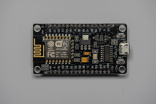
The first of the Nodemcu Development Kit had the interpretation number V0.9. The resulting age had the version number V1.0, and this fresher transformation used ESP-12E (not ESP-12), which goes with 4 MB of burst memory. The new structure goes with the CP2102 consecutive chip (not CH340) and it works honourably and without an issue.
In any case, with respect to various Chinese online vendors, there’s a clouding slip-up old enough and structure names. The ordinary name used by them for structure 1.0 is V2, and most of those V2 sheets are made by or conceivably set apart with “Amica.” Technically, it’s “NodeMCU V1.0 with ESP-12E module!”
It’s definitely not hard to use the Arduino IDE to program your board, but also a fantastic early phase for Arduino darlings to adapt themselves with the progressions incorporating the IoT. Note that when you use the board with the Arduino IDE, the Lua firmware will be eradicated and replaced by the sketch moved by you. If you have to use the Lua SDK again, it will get critical to “streak” the firmware again.
The NodeMCU programming can be also as basic as in Arduino. Therefore, The critical difference is in the pin assignment of the board.
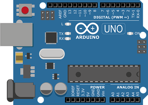
NodeMCU is extraordinary for interfacing clouds and also Arduino is incredible at chatting with various sensors. it has just a single simple pin. In this blog, we will now perceive how to interface Arduino to Board and present information on an MQTT representative. also, Arduino will take temperature readings and send the readings to nodeMCU over the sequential association.
So, NodemMCU will send an MQTT message for each pursuit it gets. In the event that you have only one sensor to screen you can straightforwardly utilize the simple info accessible on it. see this blog on the most proficient method to utilize the simple pin of the Board.
NodeMCU ESP8266 Specifications:
- Microcontroller: Tensilica 32-cycle RISC CPU Xtensa LX106
- Working Voltage: 3.3V
- Data Voltage: 7-12V
- Mechanized I/O Pins (DIO): 16
- Straightforward Input Pins (ADC): 1
- UARTs: 1
- SPIs: 1
- I2Cs: 1
- Streak Memory: 4 MB
- SRAM: 64 KB
- Clock Speed: 80 MHz
- USB-TTL subject to CP2102 is fused introduced, Enabling Plug n Play
- PCB Antenna
- Minimal Sized module to fit shrewdly inside your IoT adventures
On the Arduino side, we will take a test occasionally and send a JSON message over a soft serial to nodeMCU. If you don’t mind, note that Arduino UNO chips away at 5v and nodeMCU works at 3v3 level. So you should utilize a level shifter to associate Arduino delicate sequential pins to the nodeMCU UART port (It additionally works without level converter, however, it isn’t recommended).
More about the board
Thus, On the nodeMCU side, we have to get the messages sent by Arduino over sequential. Arduino will send the messages in JSON design. We won’t do any handling on nodeMCU (It is conceivable to deal with the messages prior to shipping off the cloud, for instance, you can contrast the current perusing and the past distributed messages and send the message just if the perusing is unique) . So, You have to have a working MQTT agent account.
When you confirm that the nodeMCU can interface with facilitating and send messages, you can associate Arduino to nodeMCU. Firstly, you should close the sequential port association with the board, at that point Connect Arduino SoftSerial Tx to NodeMCU Rx (through level shifter).
Appeared next is a model code to understand a “breathing LED” on NodeMCU:
#define LED D0 /Blue LED in NodeMCU at pin GPIO16 (D0).
#define BRIGHT 350 /max LED force (1‐500)
#describe INHALE 1250 /Inhalation time in milliseconds.
#define PULSE INHALE*1000 /BRIGHT
#describe REST 1000 /Rest Between Inhalations.
void setup()
{
pinMode(LED, OUTPUT);/LED pin as yield.
}
void loop()
{
/incline expanding force, Inhalation:
for (int i=1;i0;i‐‐)
{
digitalWrite(LED, LOW); /turn the LED on.
delayMicroseconds(i*10); /stand by
digitalWrite(LED, HIGH); /turn the LED off.
delayMicroseconds(PULSE‐i*10); /pause
i‐‐;
delay(0); /to forestall guard dog terminating.
}
delay(REST); /take a rest…
}
Written by: Charu Jain
Reviewed By: Batta Pruthvi
If you are Interested In Machine Learning You Can Check Machine Learning Internship Program
Also Check Other Technical And Non Technical Internship Programs