
Imagine you are in the middle of a spacious busy room with many lights. The light requirement of the room may not be the same all time. We can’t keep turning lights on and off, and also we can’t leave them on. It costs more. So, can you think of a solution to overcome this.
If you are thinking about IoT, you are absolutely right. So, in this article let’s see how to control two LEDs dynamically based on the brightness of the room or Smart Dual LEDs. But we can’t solely depend on smart control. So let’s also add a manual control, to make it a perfect light control.
HARDWARE USED | Smart Dual LEDs:
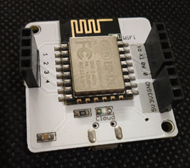
- Bolt Wi-Fi module:
The ESP8266 WIFI Module is a self-contained SOC with an integrated TCP/IP protocol stack that can give any microcontroller access to your Wi-Fi network. This module has a powerful enough on-board processing and storage capability that allows it to be interconnect with the sensors and other application-specific devices through its GPIOs. Bolt Wi-Fi module
- Light-dependent resistor(LDR): It works on the principle of photoconductivity. The passive component is a resistor whose resistance value decreases with the increase in incident light intensity.
- Light-emitting diode(LED): An LED is a semiconductor device that emits colourful light when current flows through it.
- Resistors(1- 10KΩ, 2- 330Ω): Resistors (of value 330Ω) are connected in series with the LEDs to limit the current that flows through them. Another resistance (of value 10 KΩ) is connected in series with the LDR.
- Connecting wires: Male-to-male jumper wires are used to connect the components to the Wi-Fi Module.
- BreadBoard: A breadboard is use in order to make quick electrical connections between the components.
CIRCUIT CONNECTION | Smart Dual LEDs:
Circuit visualization
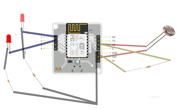
- The LDR is connect up to pins A0 and 3V3 of the Wi-Fi module to get Analog reading from the sensor.
- A resistor is connect to between the pins A0 and ground in series with LDR to restrict current through LDR.
- The LEDs (positive terminals) are connected to pins 1 and 2 of the Wi-Fi module and the negative terminals are connected to the ground through a resistor in series.
WORKING of CIRCUIT For Smart Dual LEDs:
The LDR connected to ‘A0’ pin is used to get the Analog input which depicts the brightness of the room, it is done using the voltage across it with the help of a resistor in series. The collected data is analyzed in the cloud, and it is used to predict whether either or both of the lights should be switched on or off. The LEDs are connected to digital pins 1 and 2 and to limit the current flow to avoid burning of the LEDs a resistor is added in series with them, which is further connected to ground to complete the circuit.
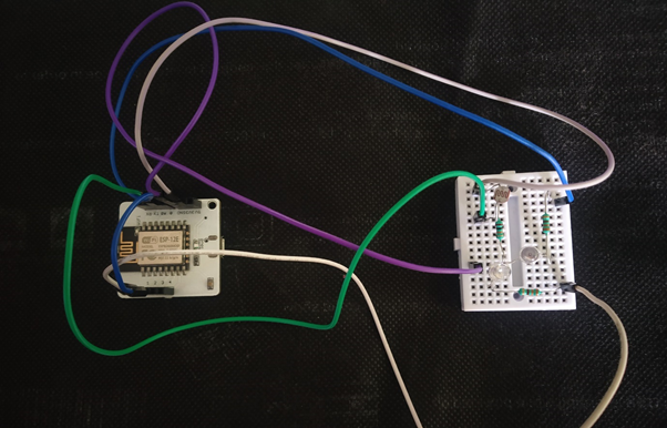
Breadboard connections:
CODE EXPLANATION:
The code is to write in HTML and JavaScript. The detailed explanation of Smart Dual LEDs is as follows:
STEP 1:
Firstly, a web page is create using HTML with title and heading for the page, and styles adds for the background and heading division. (In the style part, the ‘rgba’ function is use to create a white layer on the black background with 50% opacity, colour: #fff111 is use for yellow text in the division. Every division is style in the same manner)

STEP 2:
Two buttons are added (to select either smart control or manual control) in the body part, which when clicked triggers its respective function.

STEP 3:
Now another division is add with id ‘manually’. This division is in use to display manual control when smart control is switch off. <I> tag is use for the italic font.

STEP 4:
BOLT ESP8266 is the Wi-Fi module used. A set of predefined functions are used to control the Wi-Fi module which is imported using the link “https://cloud.boltiot.com/static/js/boltCommands.js”. Device ID and API key are set automatically (The first script block used imports the required libraries and the second script block is used for implementing the defined functions).

STEP 5:
The smart function is defined. When enabled, it gets data from the LDR sensor every ten seconds using Analog API and compares it with the pre-defined values and decides whether to switch on one LED or both the LEDs, or none depending on the brightness of the room. The Analog read function is used to read data from the LDR sensor and the setTimeout function is used to update the values for every ten seconds.

STEP 6:
A variable ‘manualdata’ is defined to store the manual control set and is displayed when opted for manual control. It has two sets of control for both operating both the LEDs.

STEP 7:
The manual function is defined that displays the control set for the user and disables automated control.

STEP 8:
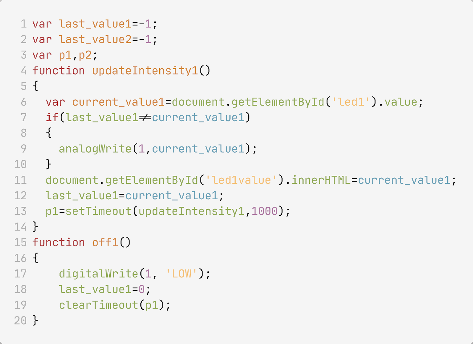
In the manual control, four functions are defined namely ‘updateIntensity1’, ‘updateIntensity2’, ‘off1’, ‘off2’. These are used to switch on, switch off or to vary the intensity of the LEDs by the pulse width modulation (PWM) technique.

complete code implemented:
<html>
<head>
<title>LED CONTROL PANEL</title>
<script type=”text/javascript” src=”https://cloud.boltiot.com/static/js/boltCommands.js“></script>
<script>
setKey(‘{{ApiKey}}’,'{{Name}}’);
var last_value1=-1;
var last_value2=-1 var p1,p2;
function updateIntensity1()
{
var current_value1=document.getElementById(‘led1’).value;
if(last_value1!=current_value1)
{
analogWrite(1,current_value1);
}
document.getElementById(‘led1value’).innerHTML=current_value1;
last_value1=current_value1;
p1=setTimeout(updateIntensity1,1000);
}
function updateIntensity2()
{
var current_value2=document.getElementById(‘led2’).value;
if(last_value2!=current_value2)
{
analogWrite(2,current_value2);
}
document.getElementById(‘led2value’).innerHTML=current_value2;
last_value2=current_value2;
p2=setTimeout(updateIntensity2,1000);
}
function off2()
{
digitalWrite(2, ‘LOW’);
last_value2=0;
clearTimeout(p2);
}
function off1()
{
digitalWrite(1, ‘LOW’);
last_value1=0;
clearTimeout(p1);
}
var manualdata='<div>’+
‘<h2>LED1 control</h2>’+
‘<button onclick=”updateIntensity1();”>’+'<b>switch on</b>’+'</button>’+
‘<button onclick=”off1();”>’+'<b>switch off</b>’+'</button>’+
‘<input type=”range” id=”led1″ value=”0″ min=”0″ max=”255″>’+
‘<p id=”led1value”></p>’+
‘</div>’+ ‘<div>’+
‘<h2>LED2 control</h2>’+
‘<button onclick=”updateIntensity2();”>’+'<b>switch on</b>’+'</button>’+
‘<button onclick=”off2();”>’+'<b>switch off</b>’+'</button>’+
‘<input type=”range” id=”led2″ value=”0″ min=”0″ max=”255″>’+
‘<p id=”led2value”></p>’+'</div>’;
var smarttime;
function smart( )
{
var current;
var xhttp = new XMLHttpRequest( );
xhttp.onreadystatechange = function( )
{
if (this.readyState == 4 && this.status == 200)
{
var obj=JSON.parse(this.responseText);
document.getElementById(“manually”).innerHTML+=obj.value;
current=obj.value;
}
}
xhttp.open(“GET”,”https://cloud.boltiot.com/remote/yourboltapi/analogRead?pin=A0&deviceName=BOLTxxx”,false);
xhttp.send();
console.log(current);
document.getElementById(‘manually’).innerHTML=”<p>sensor value:”+ current+”</P>”;
if(current>850)
{
digitalWrite(1,’LOW’)
digitalWrite(2,’LOW’)
}
else if(current>400)
{
digitalWrite(1, ‘HIGH’);
digitalWrite(2,’LOW’)
}
else
{
digitalWrite(1, ‘HIGH’);
digitalWrite(2, ‘HIGH’);
}
smarttime=setTimeout(smart,10000);
}
function manual( )
{
document.getElementById(‘manually’).innerHTML=manualdata;
clearTimeout(smarttime);
}
</script>
</head>
<body bgcolor=”#000111″ style=”width:100%;”>
<div style=”position:fixed; left:0px; top:0px; background:rgba(255,255,255,0.5); width:100%;color:#fff111;”>
<h1>LED CONTROL PANEL</h1>
</div>
<div style=”position:fixed; left:0px; top:100px; background:rgba(255,255,255,0.5); width:100%;color:#fff111;”>
<h2>SMART CONTROLS</h2>
<button onclick=”smart();”><b>ENABLE SMART CONTROL</b></button>
<button onclick=”manual();”><b>ENABLE MANUAL CONTROL</b></button>
</div>
<div id=”manually” style=”position:fixed; left:0px; top:200px; background:rgba(255,255,255,0.5); width:100%; color:#fff111;”>
<I>choose your control</I>
</div>
</body>
</html>
CONCLUSION:
In real-time applications, we won’t have small LEDs that work with 3.3v. So, to overcome this, a relay is used. A relay can be termed as an electronic switch that connects two different circuits. We can connect lights in another circuit with the required voltage supply and control it using a relay.
In this article, we have learnt how to control LEDs smartly or Smart Dual LEDs and manually using the Bolt IoT platform. We’ve also seen how to control heavy load using relays. If you are really interested in doing such useful and innovative projects, you can visit the Bolt website and check out some cool project ideas.
Written By: Batta Pruthvi and Bhavya Putta
If you are Interested In Machine Learning You Can Check Machine Learning Internship Program
Also Check Other Technical And Non Technical Internship Programs